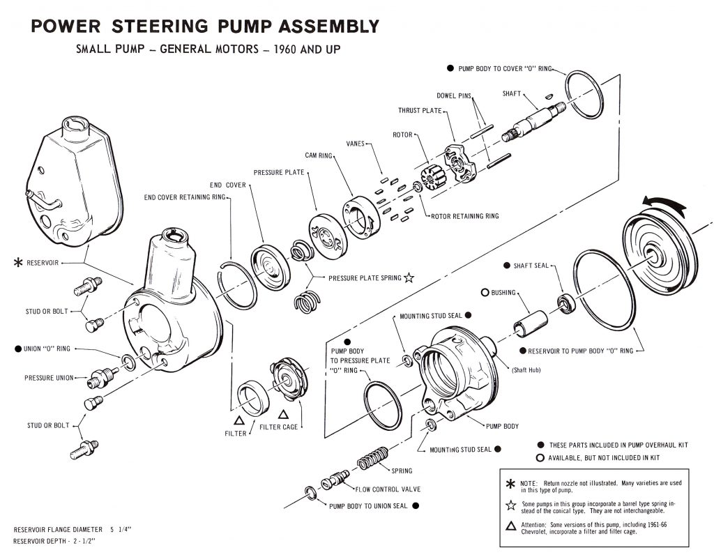
PUMP DISASSEMBLY
1. Drain fluid from pump.
2. Place unit in a vise using flat ear on shaft hub, fill spout up.
3. Remove studs or bolts and pressure union from back of reservoir.
4. Remove reservoir by flanged edge, tapping with a suitable wood block; remove key from shaft.
5. Remove flow-control valve and valve spring, two (2) mounting stud seals and pump-body-to-union seal.
6. Rotate end-cover retainer ring until break in ring is near access hole and push ring from groove with a punch and screwdriver.
7. Tap housing with soft hammer to remove end-cover which is spring loaded.
8. Carefully tap on end of shaft to remove pressure plate, rotor, rotor ring and thrust plate from body (rotor and thrust plate are attached to shaft).
9. Remove end-cover and pressure plate “O” rings from pump body.
10. Remove shaft seal from shaft hub.
• Carefully clean all parts before reassembly.
• A clean working area is important.
• Lubricate all HARD PARTS with automatic transmission fluid.
• Lubricate all SEALS AND ‘O’ RINGS with “brake assembly fluid” or automatic transmission fluid, before installation.
RE-ASSEMBLY
1. Check shaft bushing for looseness or roughness. Install new bushing if needed.
2. Press in new shaft seal with suitable installer (7/8” deep socket).
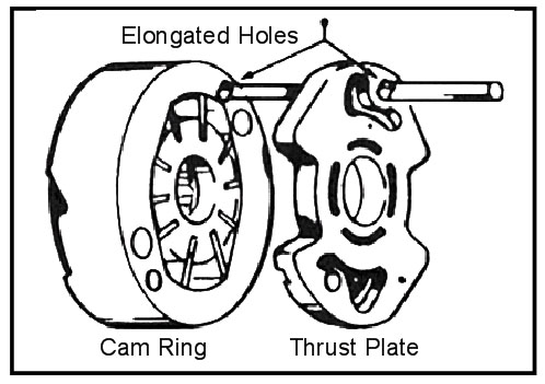
3. Replace dowel pins. Install shaft, thrust plate (worn side toward rotor) and rotor through pump body. Note: Dowel aligning holes are holes which fit snugly over dowel pins. Thrust plate and cam ring have one elongated hole and one round hole. Elongated hole is matched to dowel farthest from pressure port. Install rotor ring with arrow toward rear of pump body and pointing in direction of pump rotation (see illustration).
4. Install vanes with rounded edges toward cam ring.
5. Install pressure plate and cover “O” rings in grooves in pump body and place pressure plate in position with chambered side toward rotor; press pressure plate through “O” ring.
6. Install pressure plate spring and place end-cover in position, flanged side up. Press in end-cover far enough to install retainer ring.
7. Place flow-control valve spring and valve in pressure port. Valve is installed hex end down.
8. Place filter cage and filter over end-cover (when used). Install the two (2) mounting stud seals and pump-body-to-union seal.
9. Install large “O” ring and coat matching surface of reservoir with “brake
assembly fluid” or petroleum jelly. Install reservoir, being careful to align holes in reservoir with matching holes in pump body. Carefully tap reservoir into position with soft hammer or block of wood.
10. Place ”O” ring on pressure union, and screw union into pump body through hole in reservoir.


