NOTE: Read these instructions carefully! Important: This kit is assembled for shipping purposes only! Be sure to check all nuts and bolts for adequate torque prior to use. Don’t forget!
NOTE: Before operating the vehicle after installation test the function of the brakes under controlled conditions. make several stops in a safe area from low speed and gradually work up to normal speeds. Do not drive with untested brakes! Always utilize safety restraints when operating the vehicle.
MOUNTING INSTRUCTIONS
Step 1:
- Check to be sure that your kit has all the necessary parts needed to complete this project! (Use the supplied parts list as a check list.)
Parts List:
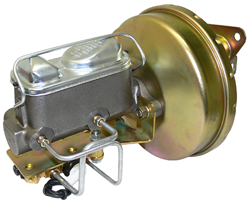
- 1 ea Booster
- 1 ea Master Unit
- 1 ea Firewall Gasket
- 1 ea Proportioning Valve (disc brakes only)
Step 2:
Tech tip: Prior to disassembly spray the nuts and bolts that you will be removing with a penetrant. (Also disconnect the battery to eliminate the risk of draining the battery or an electrical short.)
Remove the following components from your car:
- Remove the old master cylinder from your car by first disconnecting the brake lines to the master cylinder. Next, remove the push rod from the brake pedal by removing the bolt located at the top of the pedal. Then remove the old master.
- Now remove the original brake pedal.
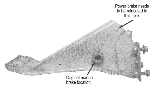
- Check for a positioning hole in the top of the pedal support. Most cars will have a 3/8” diameter hole on the top, towards the front of the car. If the hole is missing you must remove the pedal support and drill a 3/8” diameter hole in the proper location.
Step 3:
Things to prepare before assembly of the new booster and master kit.
- Remove the new master cylinder from the booster assembly.
- Bench bleed the new master cylinder to remove all the air. If all the air is removed from the master, then it will be difficult to push the piston in.
How to bench bleed:
Remove the master from the booster and place in a vice. (Be sure to clamp onto the mounting ear and not the cylinder.) Install the proper size plugs in the outlet ports of the master. Fill the master cylinder to the full line with brake fluid. Use a rounded end rod or a phillips head screw driver and push the piston in repeatedly until no bubbles are visible.
NOTE: This may take a minute or two of continuous pumping!
Step 4:
Installation of booster and master components:
- Slide the pedal up into the pedal support and insert the bolt through the top hole of the support. Do not over-tighten the nut with nylon insert. The pedal must be free from binding. (If your car originally had a power brake system you will use your original pedal. If it was a manual brake system, then you will use the one that was supplied with your specific kit.)
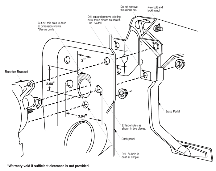
- Now drill new holes corresponding to the booster mounting studs. Also, open up the area above the large hole in the firewall for added clearance using the gasket as a template. (As shown in the diagram.) NOTE: Warranty is void if sufficient clearance is not provided.
- Install the booster with firewall gasket to the firewall using the supplied hardware. Then attach the booster push rod to the pedal. (As shown in the diagram.)
- Mounting the master cylinder to the booster. (Make sure that the master was properly bled.)
- Connect the vacuum fitting and the hose to either the intake manifold or the rear of the carburetor. Make sure that the vacuum source on the carburetor is manifold vacuum and not timed vacuum. Note: The engine must provide a minimum of 18” of vacuum for the booster to work effectively.
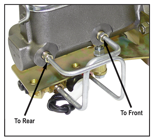
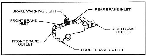
- Attach the brake lines to the master. (If your brake kit came with a combination valve then it is important that you remove any factory installed valves from the system. Failure to do this could result in a nonfunctional brake system.) Then install the combination valve.
- Run the rear line to the rear outlet on the combination valve. There are tow outlets for the front wheel on the combination valve. You have the option of running a line from each wheel to each outlet or running both lines to a T-fitting and then into one of the front outlets. (In this scenario, you will have to plug the unused outlet.) Either way is acceptable and neither routing has improved braking performance over the other. (Be sure to keep all lines away from exhaust, steering or other things that could harm.)
- When the valve is plumbed correctly and all hard lines are attached. bleed the entire system.
- If you are not using a combination valve, or you have four wheel drum brakes, you will need to run one line from the master cylinder to the front and one to the rear. The outlet closest to the booster will feed the front brakes. We recommend that you use a 10lb residual valve on both the front and rear drum brakes to provide a firmer pedal feel.
- Reconnect the battery and start the engine. Test the brakes. If the pedal goes to the floor or is very spongy then bleed the system once again.
- Test drive the car in a safe location before driving.
Picture of an original 67-70 Mustang pedal support. To install power brakes you must move the pedal pivot point from the manual brake location to the top hole in the pedal support. The hole is 3/8” in diameter. If the hole is missing you must remove the pedal support and drill a 3/8” diameter hole in the proper place.

