Click here for the printable PDF installation instructions.
Please read these instructions completely before starting your installation.
Remember the basic rule for a successful installation: Measure Twice, Weld Once!
1.Start by supporting the truck on 4 jack stands. The truck should be sitting at approximately the same an- gle as it does on the ground or slightly lower in front.
2. Remove all the old suspension components from the frame. The front spring shackle mounts riveted in the frame are used for a measuring point. The top of the frame rail should also be flattened in the area where it is turned up for the old steering box mount.
3.The front frame section is to be boxed, using the boxing plates supplied. The plates fit up against the rear of the radiator crossmember. You can grind the inside edges of the frame rails flat so the plates lay flat against them, but do not grind off too much material as the rails will become too thin. The plates can set on the lower flanges of the rails in the front, but most of the flange will eventually be trimmed away for the rack C-notch and crossmember clearance. Fit the plates, weld and grind smooth.
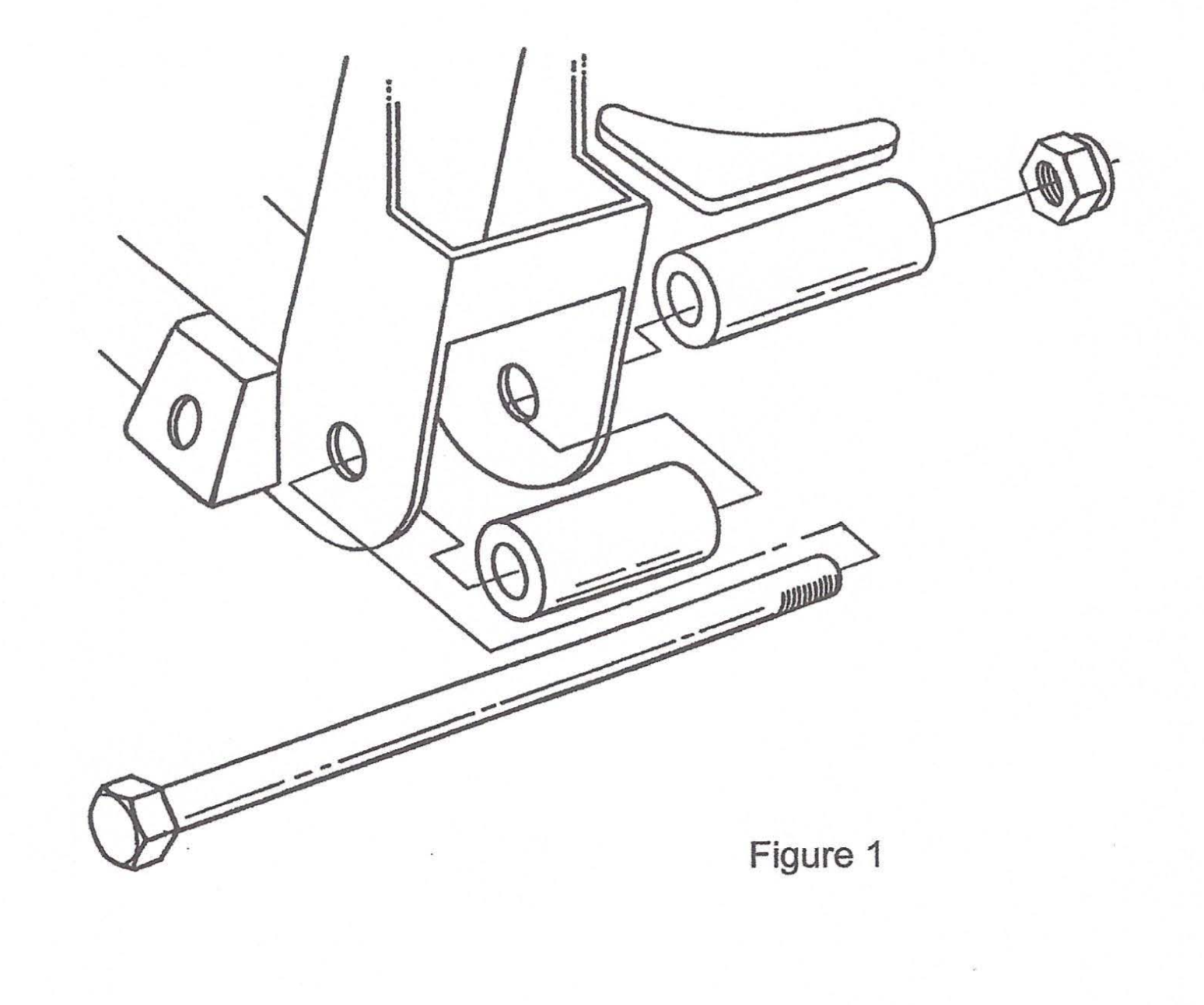
4.If you purchased a complete 1.F.S.Package from HEIDTS, it was supplied with Full Lower A-Arms. Be- gin by installing the Spacers onto the crossmember. The holes where the lower control arms attach to the Crossmember must be enlarged to 5/8″. Mount the Crossmember Spacers and the Rear Spacers which were supplied with the Lower Control Arms onto the Crossmember as shown in Figure 1 using the supplied Inner Bushing Bolts, Nuts and a temporary spacer under the Nuts. DO NOT use the A- Arms for this operation as the welding heat will melt the rubber bushings. Tighten the Bolts and Nuts tight. Weld the Rear Spacers to the Crossmember all around. Weld the Crossmember Spacers as far as possible inside the crossmember on both ends. Position the Gussets horizontally, not vertically, against the Rear Spacers and the back of the Crossmember. Weld Gussets to Spacers and Crossmember. When it cools, remove the bolt.
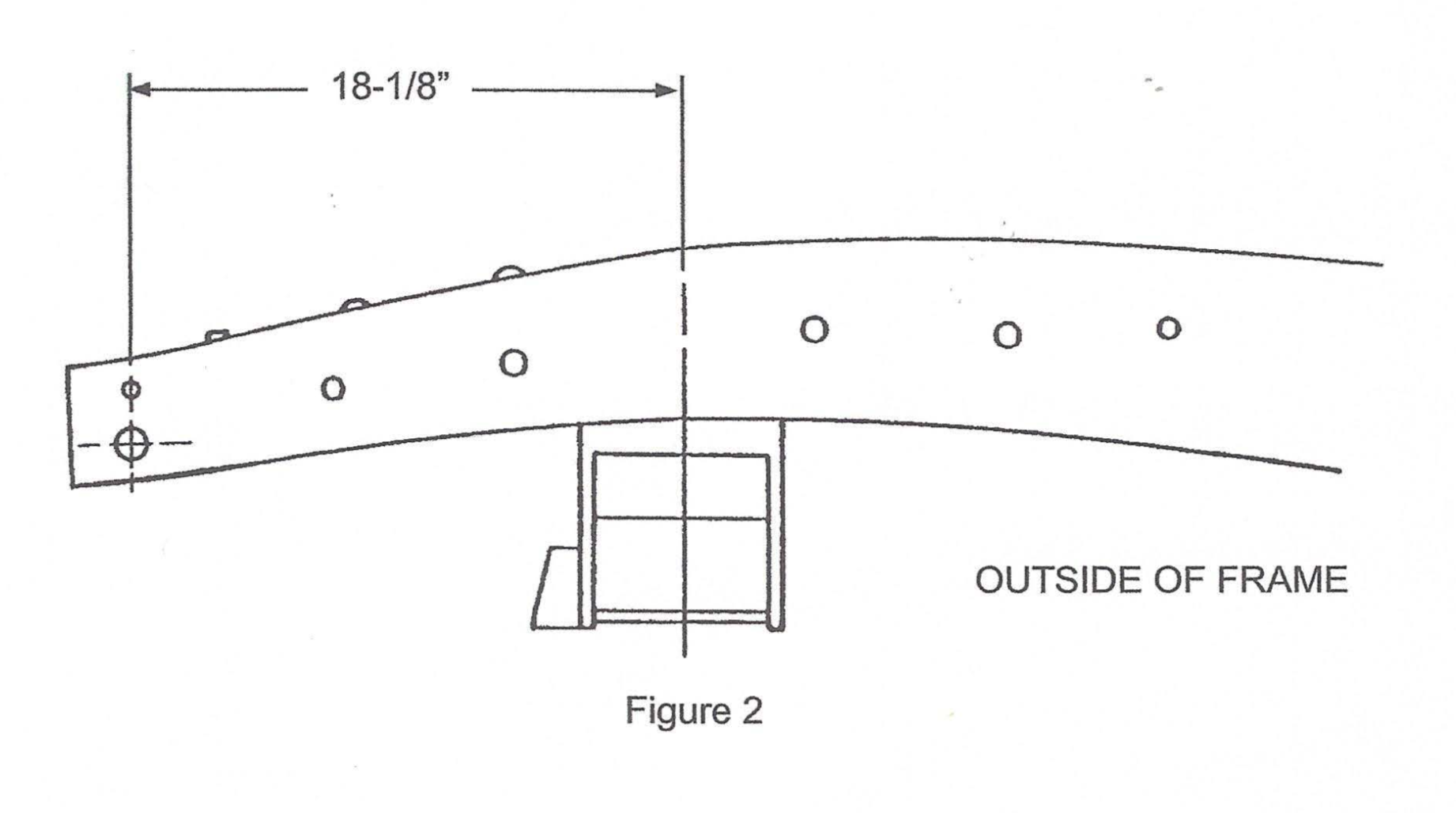
5.Now install the new crossmember. Measure straight back 18-1/8″ from the center of the front spring shackle hole in the frame and make a vertical line as shown in Figure 2. This will be the center of the crossmember and the spindle centerline. Slip the crossmember up into the frame and center it on the centerline mark. If it does not fit up into the frame, grind the sides of the crossmember uprights so you can get it into this position. Make sure that the crossmember is seated fully on the underside of the frame. Tack weld in place.
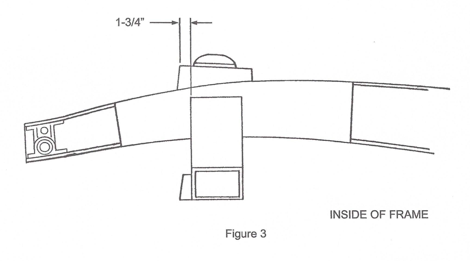
6. Next are the spring towers. They sit on top of the frame rails, and are located 1-3/4″ forward of the front of the crossmember, as shown in Figure 3. The higher side of the spring towers goes toward the front. Seat them fully against the frame, grind to fit the tops of the frame rails, clamp in place, then tack weld.
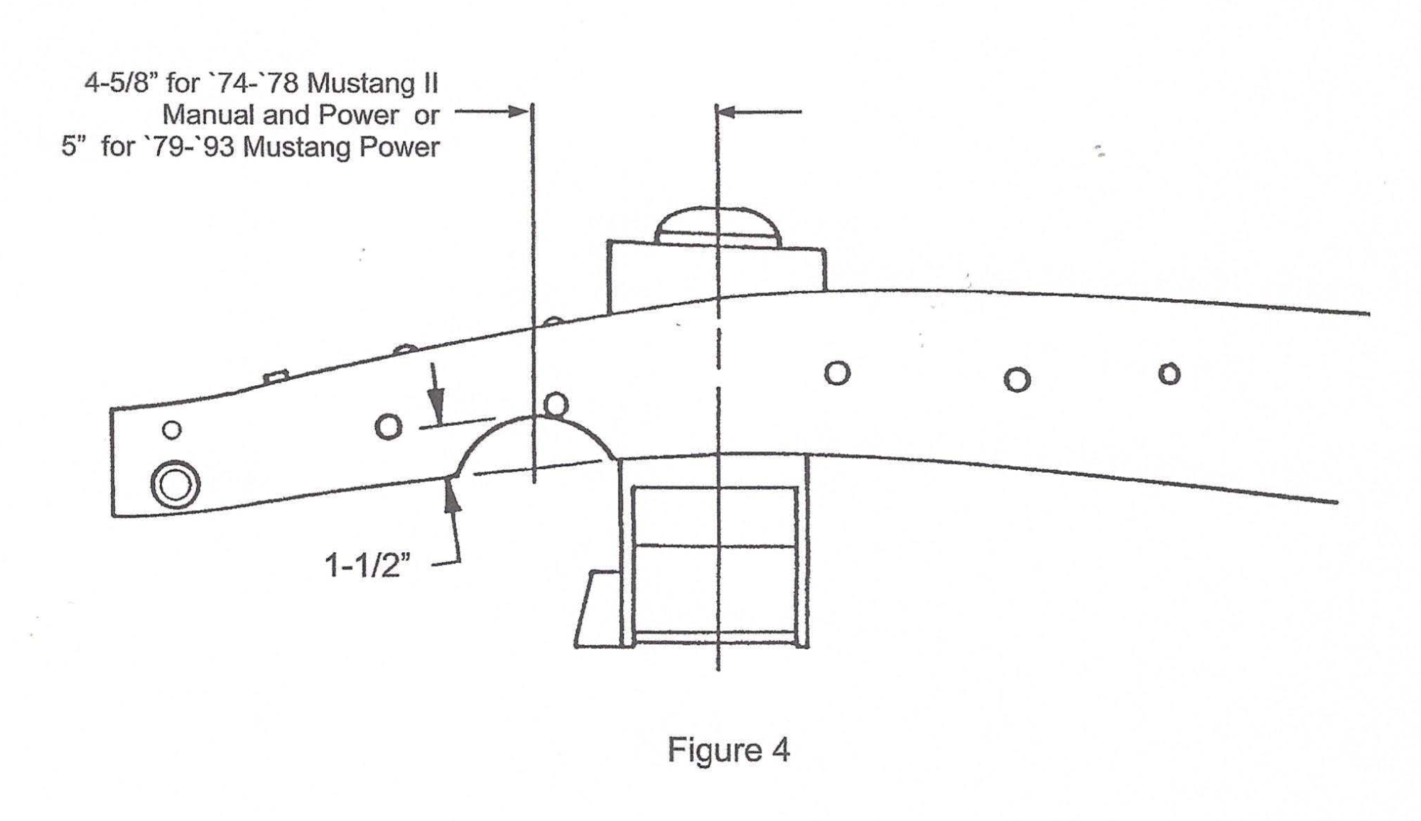
7.The C-notch for the rack is the last part to be done. Measure forward from the centerline 4-5/8″ for ’74- ’78 Mustang II power and manual or 5″ for ’79-’93 Mustang power rack, and up 1-1/2″ and make a mark. Now draw a 2-1/8″ radius, using your mark as the top of the radius. See Figure 4. Trim out the material marked, leaving about 1/8″ to work with, and then try the rack and the C-notch filler piece. Fin- ish grind the notch for fit and location, and tack the filler pieces in place. Remove the rack.
8.Now go ahead and finish weld all the parts in place. M.I.G. welding works best for this, however any type of properly done arc welding will be fine. Weld the crossmember and spring towers all around. The spring towers can also be welded on the inside of the vertical gussets on the sides of the frame rails. Weld all around the rack C-notch fillers also.
9. If you are using stock components, you will need to install strut rod brackets, part no. MP-003-1, purchased separately. Continue on to Step 10. If not, then you are finished and proceed on to the assembly and alignment of your suspension.
OPTIONAL STOCK STRUT ROD INSTALLATION
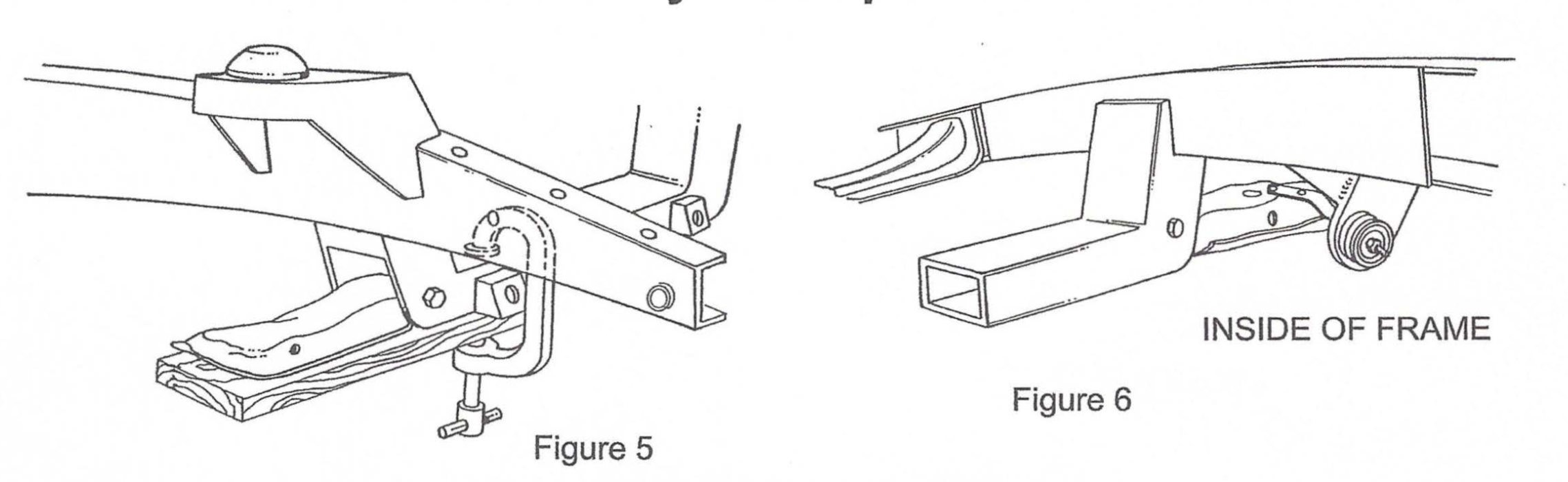
10. If you are using factory lower control arms and strut rods you will continue here. Use the lower control arm and strut rod for locating the rear strut rod supports and gussets. Using a 2 x 4 and a C-clamp, install the con- trol arm as shown in Figure 5.
11. Install the strut rod onto the control arm. Now, assemble onto the strut rod the large rubber bushings, in- cluding the cupped washers, and the strut mount plate. Be certain to fully tighten the nut on the strut rod to its’ fully seated position. See Figure 6. There are two rubber bushing sets available; the standard replacement and the improved set. We recommend the improved set, as it provides more stability to the front suspension. The Pinto and Mustang strut rods are different angles. We recommend the use of Pinto strut rods, as they are bent less than the Mustang strut rods and will position the strut rod plates more closely under the frame rails. The Mustang strut rods may be used, however, but must be heated in the elbow area and bent outward. The rod is bent outward until the strut mounting plate lines up to the frame rail. The strut rod will act as an align- ment fixture while you tack weld the mount plate in place, then tack weld the gusset in place. Remove the strut rod, bushings, and arm, and finish welding to the frame and each other.
That’s all there is to it. Go ahead and finish the assembly of the rest of the s_uspension components. After the rest of the truck is assembled and back on the ground, do your front end alignment as fol- lows:
Caster 1° positive Camber 1/2° positive Toe-In 1/8″ ± 1/8″
Check the installation after 100 to 200 miles, including the alignment. The springs should have settled down by now, so the lower control arms are parallel to the ground. If the car still sits too high, you may need to change to softer springs, or you can cut up to one coil off the bottom of the springs to get the lower arms horizontal. If it sits too low, stiffer springs or HEIDTS new Spring Spacers are available. If you have any questions during or after the installation, feel free to call us for technical as- sistance.