Click here for the printable PDF installation instructions.
Please read these instructions completely before starting your installation.
Remember the basic rule for a successful installation: Measure Twice, Weld Once!
1.) Start your installation by supporting the truck on 4 jack stands. The truck should be sitting on the approximate angle that it does on the ground, or slightly lower in front.
2.) Begin by removing all the stock suspension components from the frame. The front crossmember should be left in place.
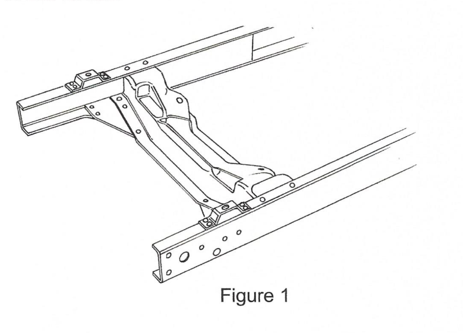
3.) Boxing the rails is next. The flange on the left rail should be flattened where the old steering box was mounted and made straight and true. The boxing plates are to stand square on the lower rail flange. The frame rail top edges should be ground straight so the boxing plates fit tight to the rail edges. Do not grind too much off the rails. The boxing plates are then clamped in place, with the front end of the plates against the back of the stock crossmember. Weld in short sections at a time in alternating locations to minimize warpage. It is also a good idea to clamp a bar across the rails to hold them in place during welding. Grind smooth when done. Figure 1.
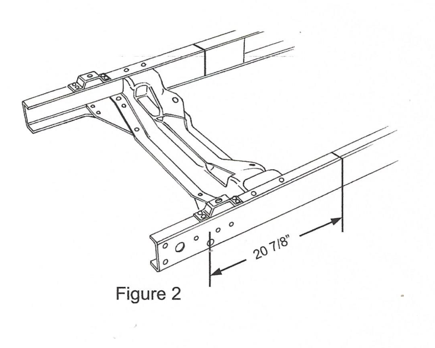
4.) Measure back 20-7/8″ from the center of the front shackle hole in the frame and scribe a line around the rail. See Figure 2. This scribed line is the spindle centerline.
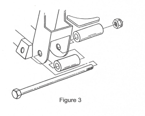
5.) If you purchased a complete I.F.S. Package from HEIDTS, it was supplied with Full Lower A-Arms. Begin by installing the Spacers onto the crossmember. The holes where the lower control arms attach to the Crossmember must be enlarged to 5/8″. Mount the Crossmember Spacers and the Rear Spacers which were supplied with the Lower Control Arms onto the Crossmember as shown in Figure 3 using the supplied Inner Bushing Bolts, Nuts and a temporary spacer under the Nuts. DO NOT use the A-Arms for this operation as the welding heat will melt the rubber bushings. Tighten the Bolts and Nuts tight. Weld the rear Spacers to the Crossmember all around. Weld the Crossmember Spacers as far as possible inside the crossmember on both ends. Position the Gussets horizontally, not vertically, against the Rear Spacers and the back of the Crossmember. Weld Gussets to Spacers and Crossmember. When it cools, remove the bolt.
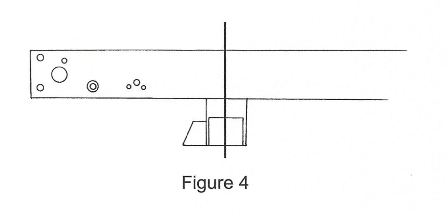
6.) Trial fit the new crossmember up into the rails centering it on the scribed spindle centerline. See figure 4. If it does not quite fit into the frame, slightly grind the upright ends of the crossmember until you can get it into place. Make sure that the crossmember is fully seated on the underside of the frame. Tack weld in place, double check the location and weld in place. welding all around both ends, top, side, and the underside of the bottom of the frame.
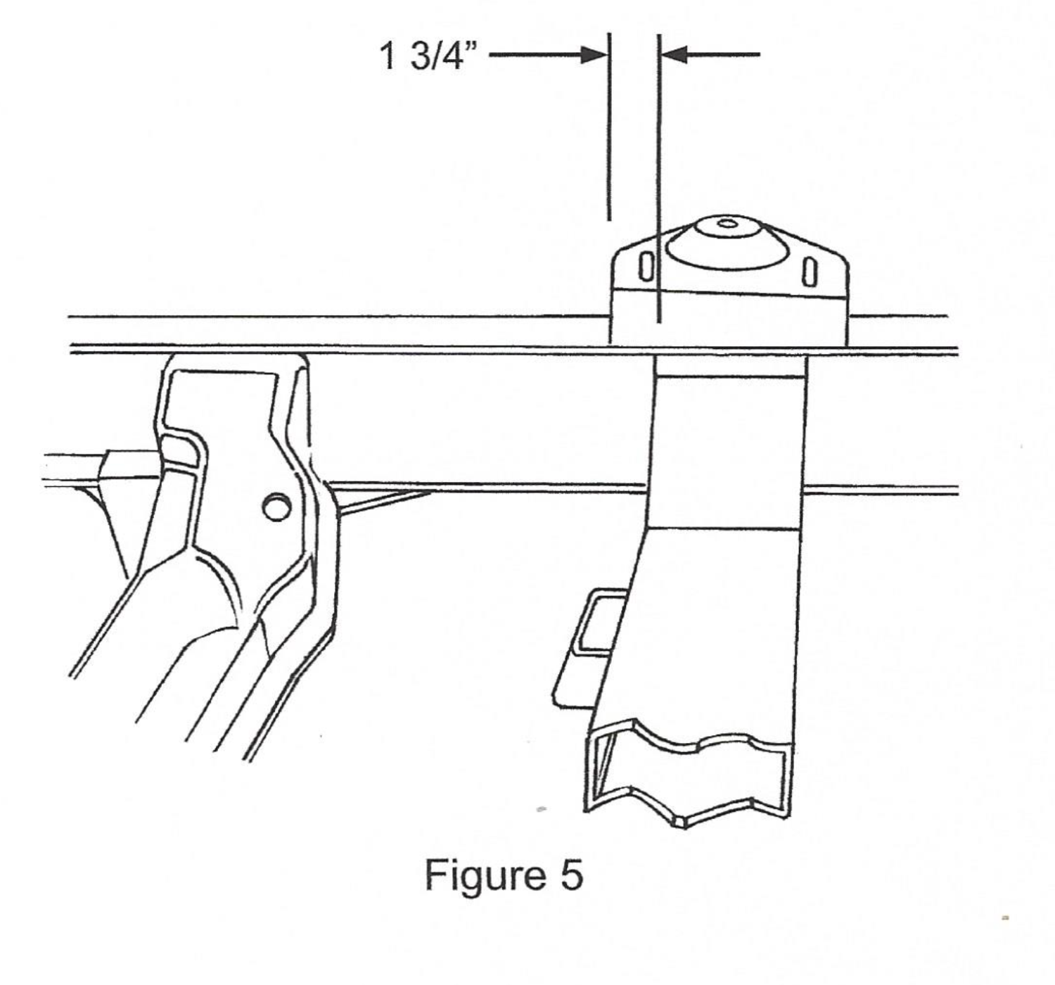
7.) Next are the spring towers. They sit on top of the frame rails. They are profited for your frame and are located as shown in Figure 5. They are 1-3/4″ forward from the front of the crossmember, measuring as shown in Figure 5. The high side of the spring tower goes towards the front end of the frame. Clamp in place, double check your dimensions, and weldd all around, including the gusset flanges not he sides of the rails. For added strength, you can also weld the inside of the gusset flanges.
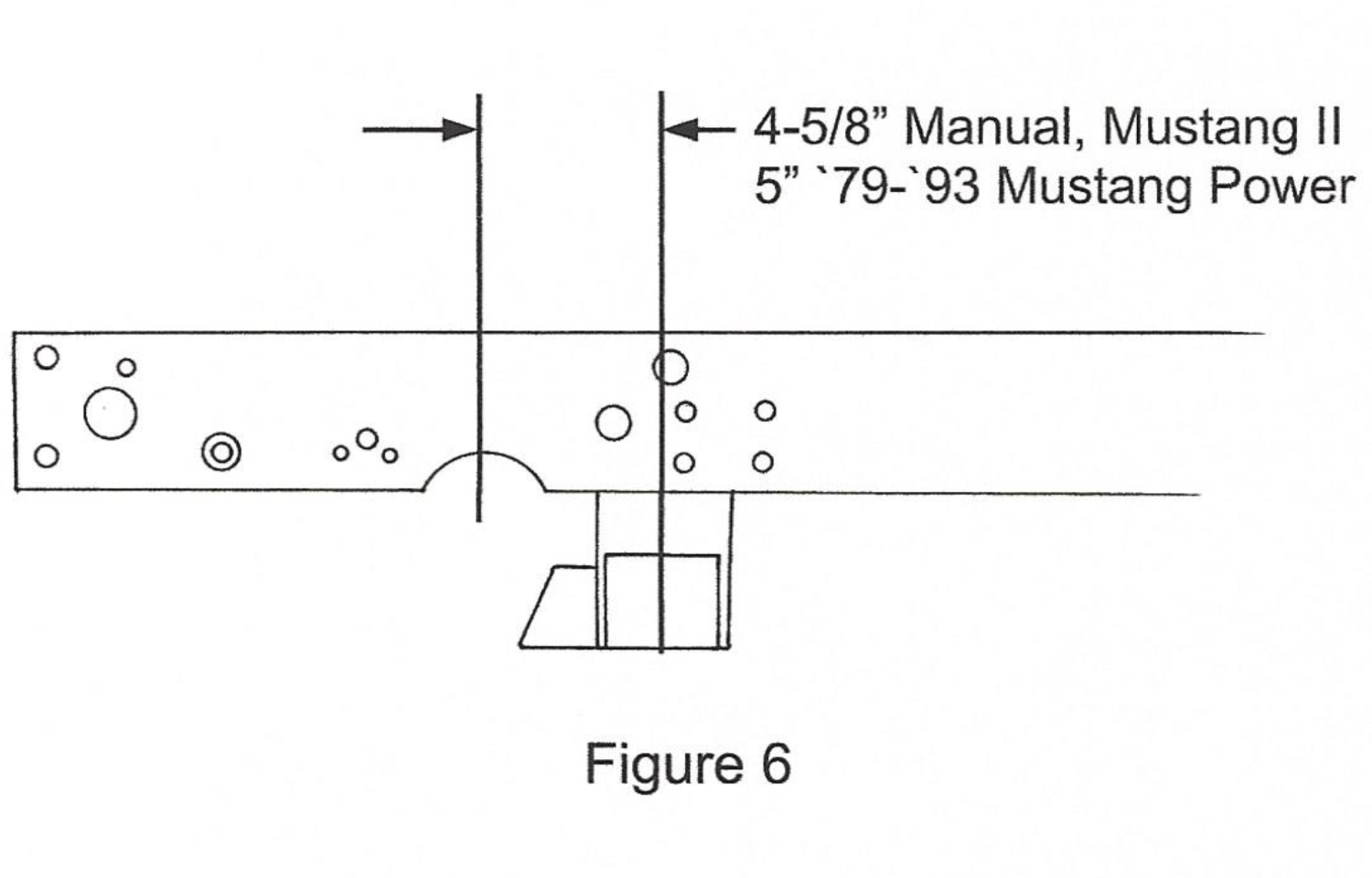
8.) The C-notch for the rack is the last part to be done. Measure forward from the centerline 4-5/8″ for manual rack and ’78-’78 Mustang II power rack, or 5″ for ’79-’93 Mustang power rack, and made a mark. See Figure 6. Use the C-notche pieces to scribe a radius to cut. Trim out the material marked, leaving about 1/8″ to work with, fitting the C-notch pieces and rack in place as you go. You will also need to trim a portion of the rear stock crossmember for rack clearance. When the rack fits in place, remove the rack and weld the C-notch pieces in place, then grind smooth.
If you are using stock components, you will need to install strut rock brackets, purchased separately, part no. MP-003. Continue on to Step 9. If not, then you are finished and proceed on to the assembly and alignment of your suspension.
Optional Stock Strut Rod Installation
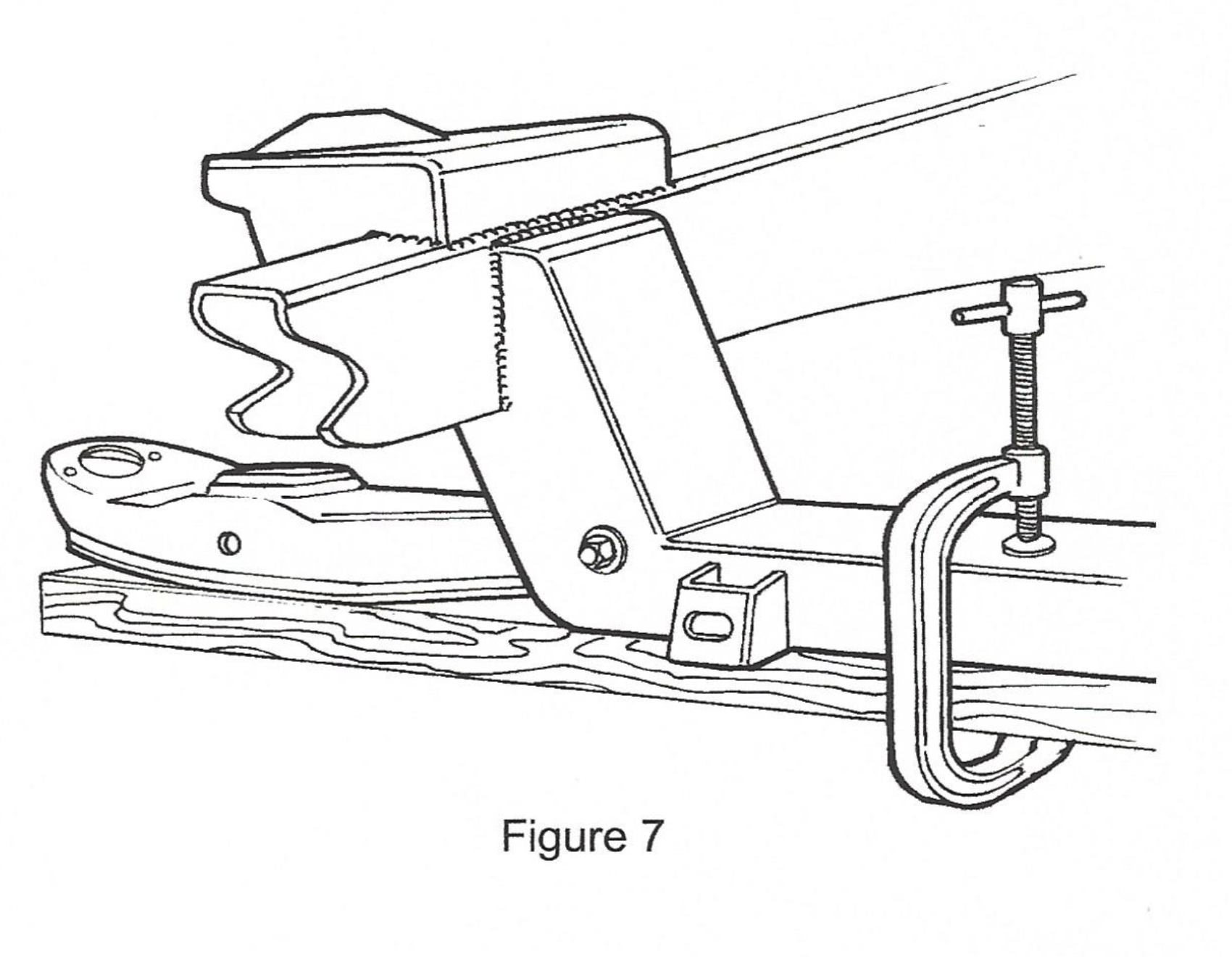
9.) If you are using factory lower control arms and strut rods you will continue here. Use the lower control arm and strut rod for locating the rear strut rod supports and gussets. Using a 2×4 and a c-clamp, install the control arm as shown in Figure 7.
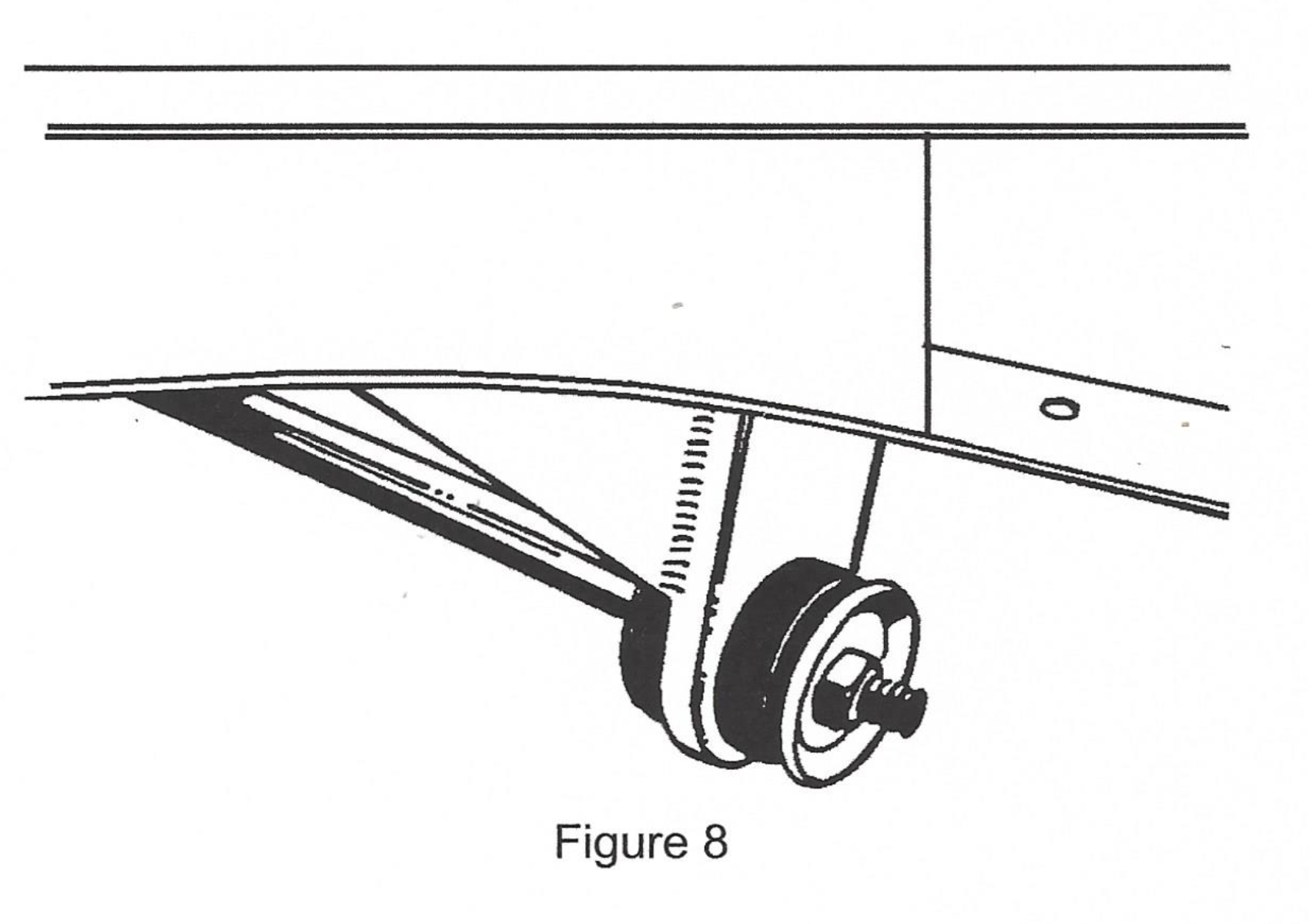
10.) Install the strut rod onto the control arm. Now, assemble onto the strut rod the large rubber bushings, including the cupped washers, and the strut mount plate. Be certain to fully tighten the nut on the strut rod to it’s fully seated position. See Figure 8. There are two rubber bushing sets available; the standard replacement and the improved set. We recommend the inmporved set, as it provides more stability to the front suspension. The Pinto and Mustang strut rods are different lengths. We recommend the use of Pinto strut rods, as they are bent less than the Mustang strut rods. You will find that with either strut rod the strut rod plate does not line up with the bottom of the frame rail. The strut rod must be heated in the elbow area and bent outward. The rod is bent outward until the strut mounting plate lines up to the frame rail. you will find that because the Pinto strut rod is initially bent less and requires much less bending. The strut rod will act as an alignment fixture while you tack weld the mount plate in place, then tack weld the gusset in place. Remove the strut rod, bushings, and arm, and finish welding to the frame and each other.
Caster 1 deg Positive
Camber 1/2 deg Positive
Toe-In 1/8″ +- 1/8″
Check the installation after 100 to 200 miles, including the alignment. The springs should have settled down by now, so the lower control arms are parallel to the ground. If not, we recommend that you change to softer springs, or you can cut up to one coil off the bottom of the springs to get the lower arms horizontal.