THE PICTORIAL ILLUSTRATIONS IN THIS INSTRUCTION SHEET ARE FOR DEMONSTRATION PURPOSES. YOUR MASTER CYLINDER MAY VARY IN SIZE AND SHAPE.
IF THERE IS ANY CONFUSION AND/OR LACK OF UNDERSTANDING PER THESE INSTRUCTIONS, CONSULT THE SERVICE MANUAL FOR YOUR MAKE, MODEL AND YEAR.
WARNING: Do not attempt to install this master cylinder without bench bleeding it prior to installation on the vehicle. Bench bleeding removes air from the cylinder bore. Without bench bleeding, satisfactory braking will be difficult to obtain.
Use only new brake fluid that meets or exceeds DOT-3 specifications. A master cylinder may be bench bled in one of the following methods:
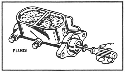
METHOD A: Bench bleeding using Outlet Port Plugs (Figure 1)
- Clamp master cylinder securely by mounting flange in a bench vise.
- Remove and discard factory installed protective plugs from the outlet ports and place a catch container under the master cylinder.
- Fill the reservoir with new brake fluid. When the fluid begins to drip from the outlet port(s), securely install threaded plugs. This provides lubrication to the piston seals before bleeding.
- Using a bleeding tool or suitable blunt stroking tool, begin slowly depressing the master cylinder piston using 3/4 to 1 inch strokes. NOTE: For quick-take-up or step-bore master cylinders, WAIT 15 SECONDS BETWEEN STROKES to avoid aeration of the fluid. Continue this procedure until the piston cannot be depressed more than 1/8 inch and no air bubbles are visible in the fluid reservoir.
- Remove the master cylinder from the vise and install on the vehicle, leaving the plugs installed.
- Remove one plug at a time and connect the steel brake lines from the vehicle to the master cylinder.
- The wheel cylinders and calipers must now be bled to remove any remaining air from the system. Refer to the Service Manual or a bleeding sequence guide for the proper bleeding procedure.
Caution: Take care to avoid spraying brake fluid with open reservoir.
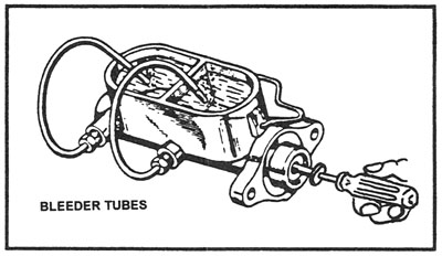
METHOD B: Bench Bleeding using Bleeder Tubes (Figure 2)
- Clamp master cylinder securely by the mounting flange in a bench vise.
- Thread bleeder tubes into the outlet ports of the master cylinder and bend the tubes into the master cylinder reservoirs. Secure the tubes to make sure they stay in place.
- Fill the reservoir with new brake fluid to approximately 1/4″ from the top. Be sure the ends of the tubes are covered by the brake fluid.
- Using a bleeding tool or suitable blunt stroking tool, begin slowly depressing the master cylinder piston using 3/4 to 1 inch strokes. NOTE: For quick-take-up or step-bore master cylinders, WAIT 15 SECONDS BETWEEN STROKES to avoid aeration of the fluid. Continue this procedure until the piston cannot be depressed more than 1/8 inch and no air bubbles are visible in the fluid reservoir.
- Remove master cylinder from vise and install on vehicle.
- Now remove the bleeder tubes and nuts for the outlet ports and attach the vehicle’s brake lines.
- The wheel cylinders and calipers must now be bled to remove any remaining air from the system. Refer to the Service Manual or a bleeding sequence guide for the proper bleeding procedure.
NOTES:
- When bench bleeding the master cylinder while mounted on the vehicle, be sure the master cylinder is level. It may be necessary to raise the back end of the vehicle to get the master cylinder level.
- If the instrument panel brake warning light is illuminated with the ignition switch on, depress brake pedal several times. If warning light does not go out, bleed system again.
No or Low Pedal Condition Testing of Combination/Proportioning Valve
- Using test light, attach clip to a positive and touch the point of the tester to the electrical connection of the combination valve.
- If NO light goes on, the valve system is operating correctly. No further testing is required.
- If light goes on, this indicates the pressure differential valve in the combination valve is stuck in front or rear position.
- Bleed brake system to determine which system, front or rear is not getting proper flow of fluid; one system will squirt out of bleeder, other system will trickle out.
- The system with the flow must be opened for flow to alter the pressure on opposite side of pressure differential valve to center valve.
- Slowly depress pedal with steady pressure until light goes out. When light goes out, close bleeder.
- Your system is now centered. Bleed complete system following enclosed bleeding instruction.
BLEEDING BRAKES
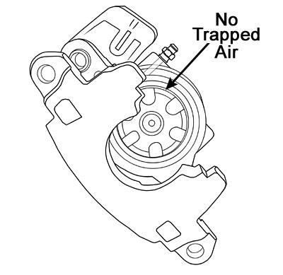
WARNING: Sometimes when a bleeder screw faces up the brakes cannot be bled! With some calipers the bleeder screw hole is drilled on an angle. Mounting the calipers with the bleeder screw facing upward will not allow you to remove all the air from the bore. Always be sure the bleeding hole is at the 12:00 position on the bore!
1.) TYPICAL MOUNTING POSITION
Does not allow for proper bleeding of brake system.
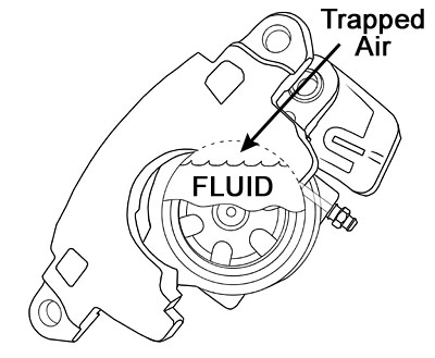
2.) ROTATED POSITION (Bleeder screw pointed up)
Still does not allow proper bleeding of brake system. This is the most common mistake made in improper brake bleeding.
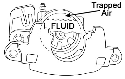
3.) CORRECT ROTATED POSITIONING
Allows for all trapped air to escape for proper bleeding of system.
