Want to get your Blazer a little closer to terra firma? Aldan American has just what you need, whether it’s a coilover conversion kit for a ’63-’87 C10, a ’73-’87 2WD Blazer, or a ’67-’72 Blazer—exactly what Rodney needed for his 1970 Chevy K5 2WD Blazer, our project vehicle.
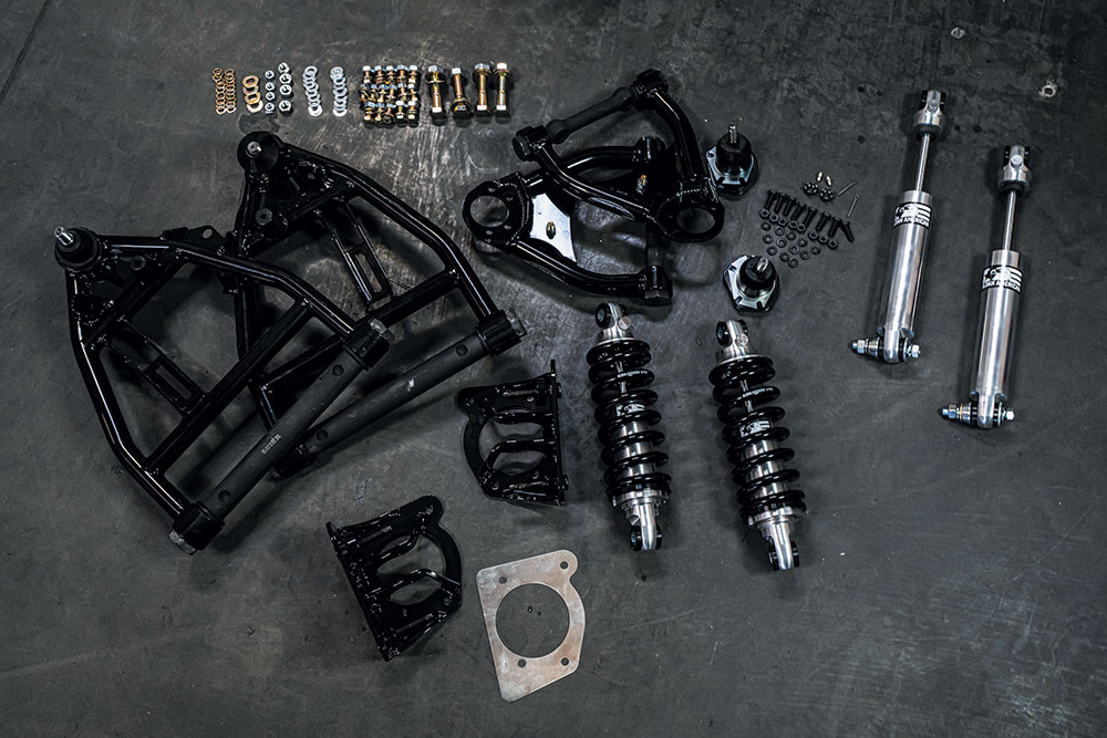
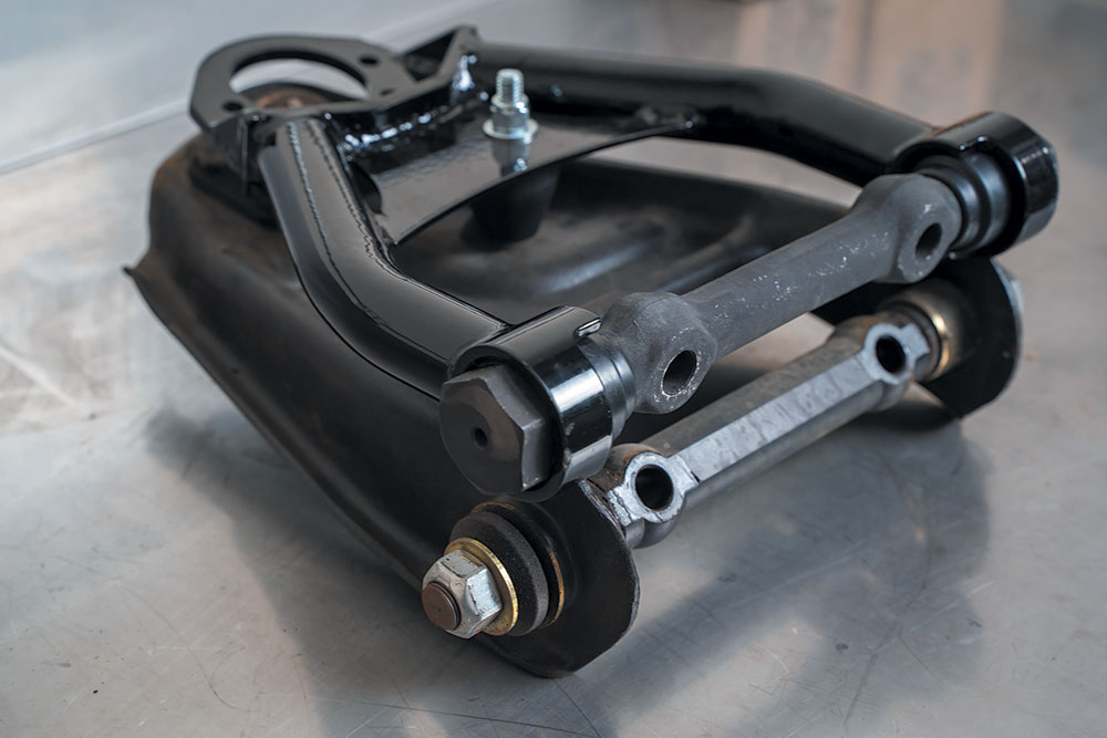
Included in the kits are two Aldan Phantom Series 13-inch single adjustable coilover shocks, the upper control arm brackets, POL tubular upper and lower control arms with ball joints, the C10 crossmember cutting template, and all the brackets and hardware needed to convert the 2WD factory front crossmember to ride-height adjustable Aldan coilovers.

Aldan offers two kits, one for a small block Chevy (Part #300136, MSRP: $2,549.95), and another for a big block (Part #300137). There are also three different rear shock absorber kits, depending on your ride height and whether the rear has coils or leaf springs.
Using the tools listed in sidebar (page XX), this kit works with the factory crossmember and will convert the front suspension to fully adjustable coilover shocks with tubular control arms. Aldan adjustable coilovers will add better performance, handling, and ride quality to your Blazer. We also wanted to give a shout out to Jimmy, one of Aldan’s online suspension techs, who helped us determine which parts were used on this install.
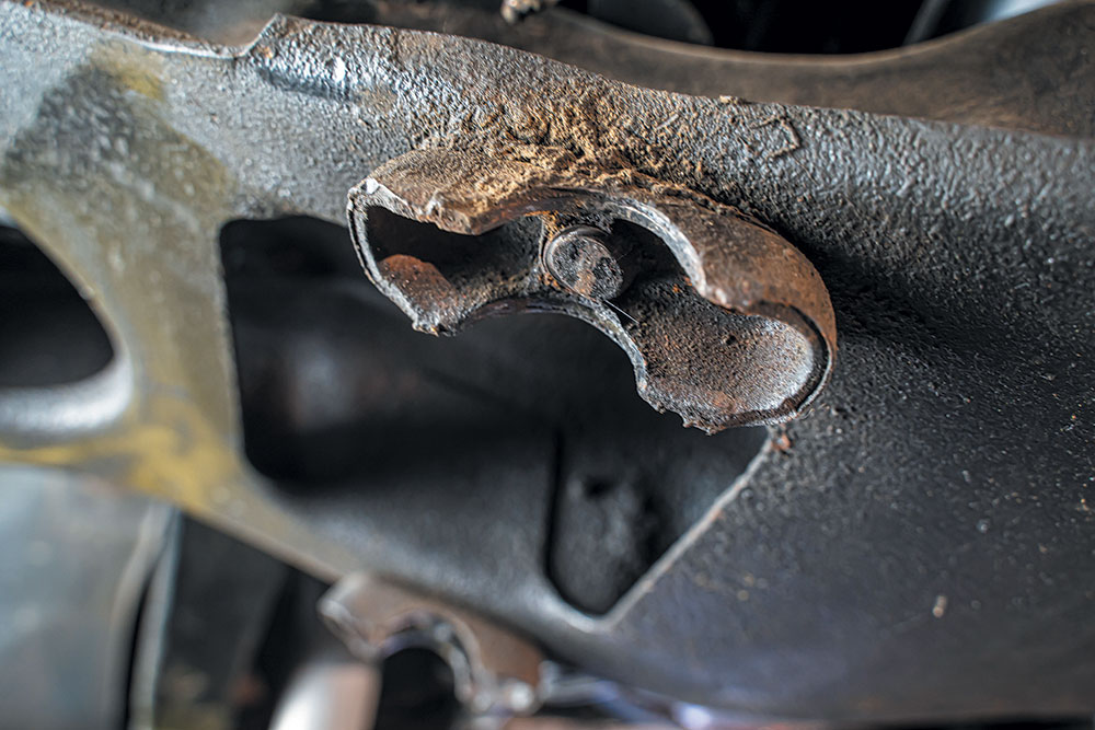
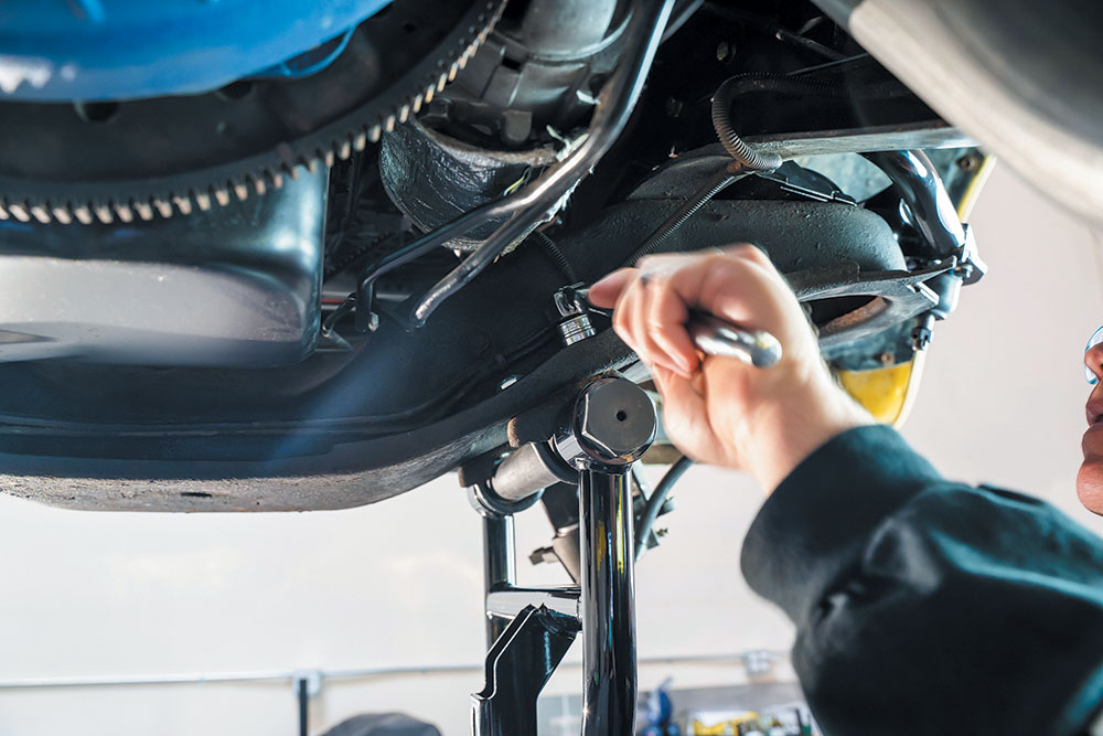
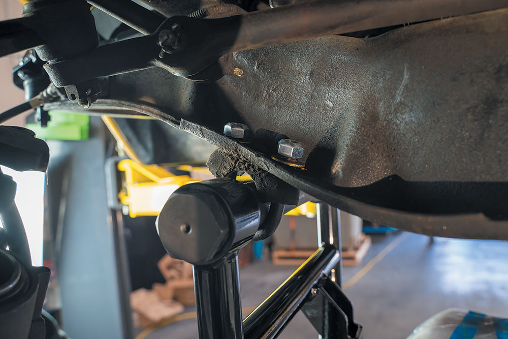
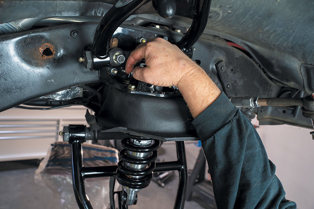
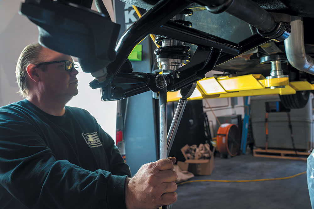
ALDAN UPPER COILOVER BRACKET INSTALLATION
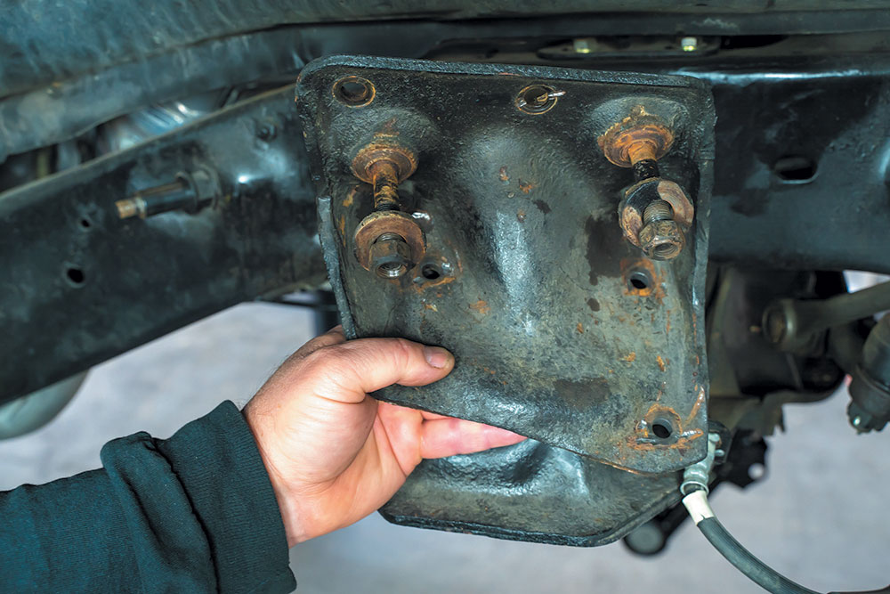
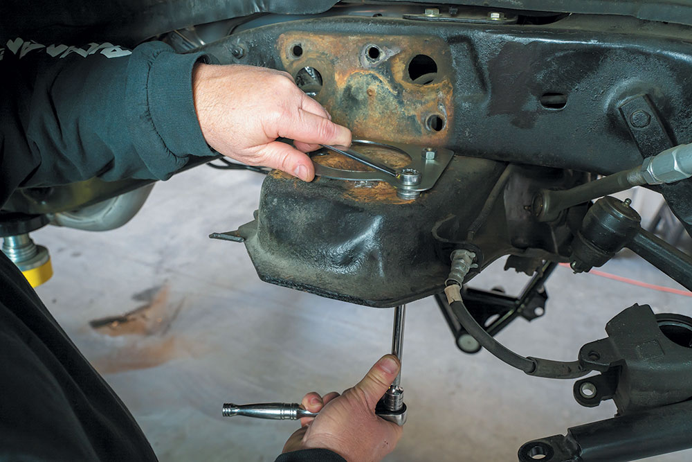
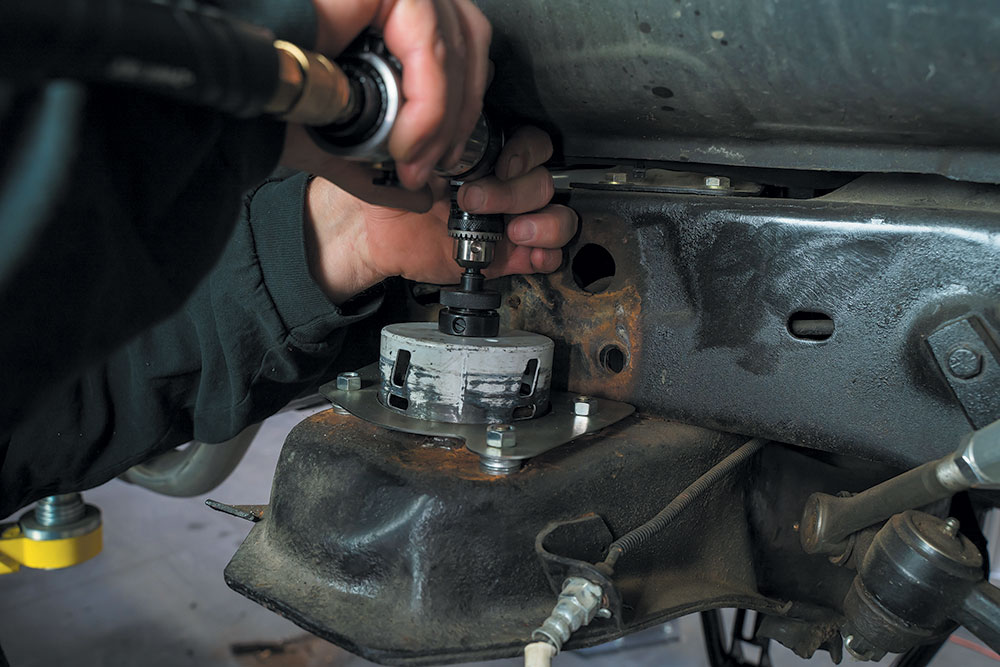
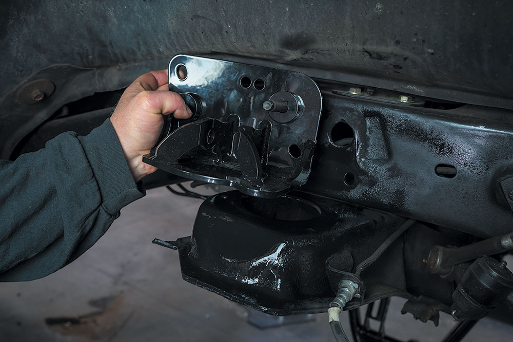
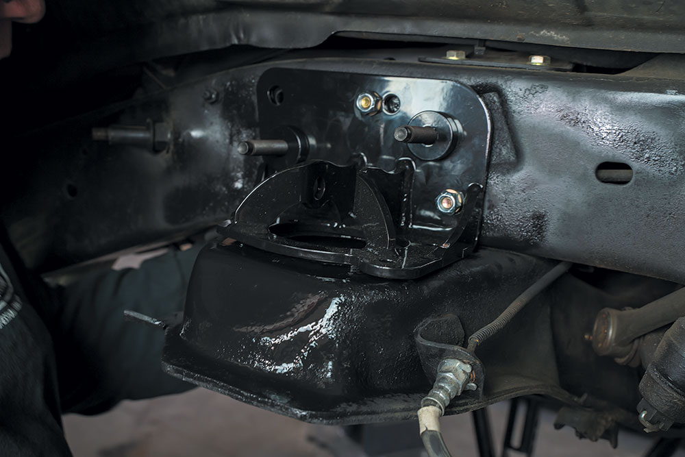
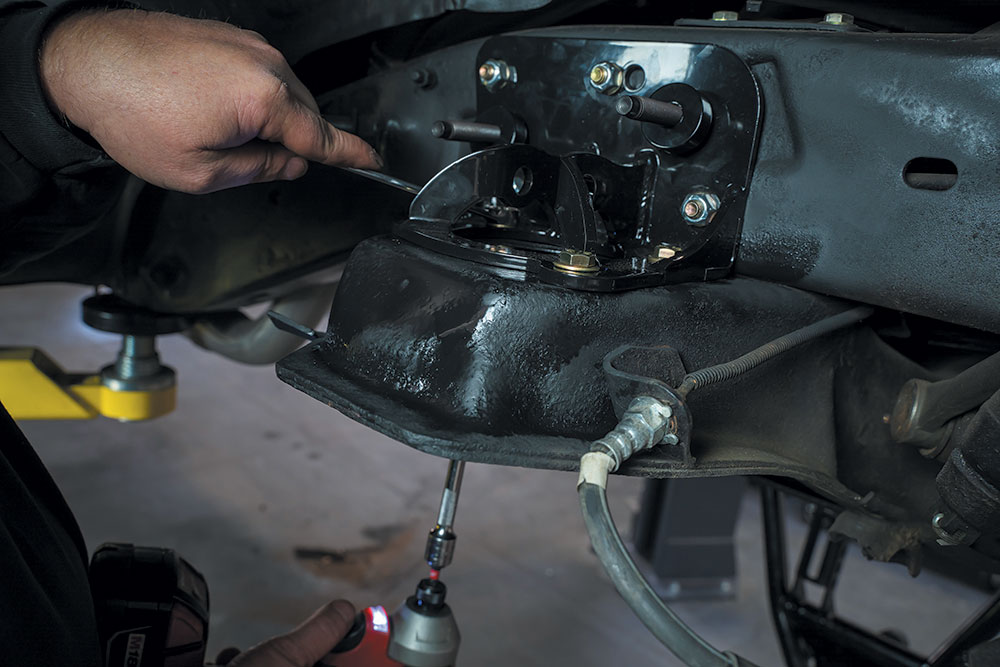
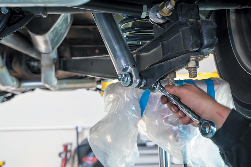
With the hardware installed and the bracket fitting correctly, torque the bolts to:
3/8-inch bolt torque spec: 30 lb-ft
7/16-inch bolt torque spec: 50 lb-ft
1⁄2-inch bolt torque spec: 75 lb-ft
5/8-inch bolt torque spec: 75 lb-ft
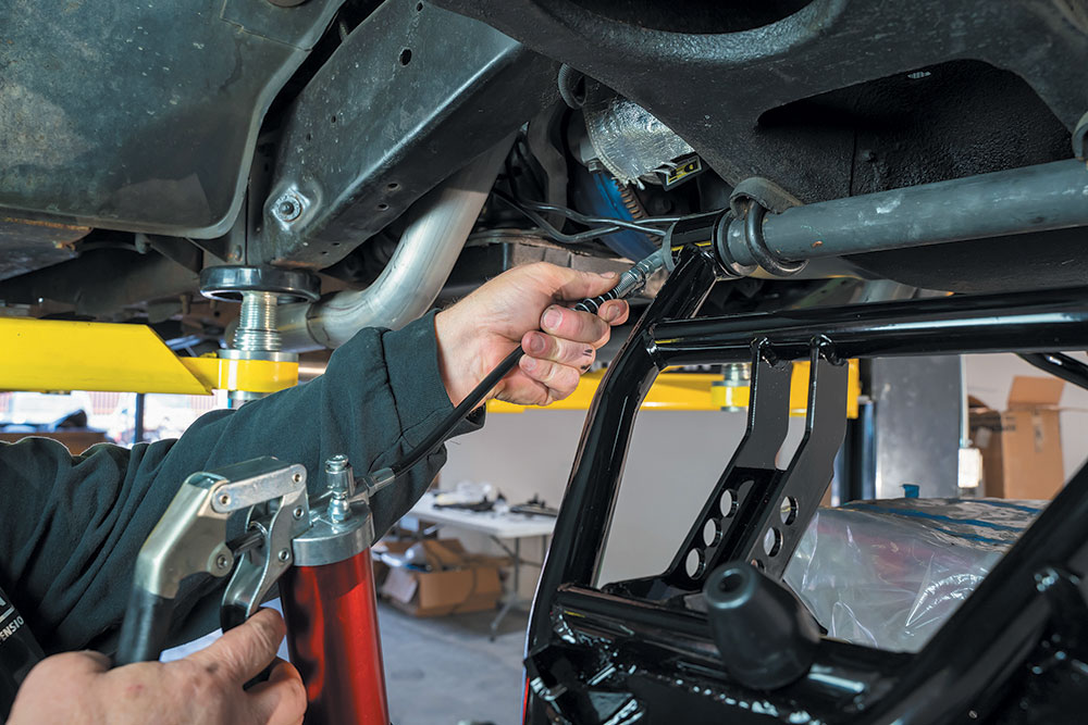
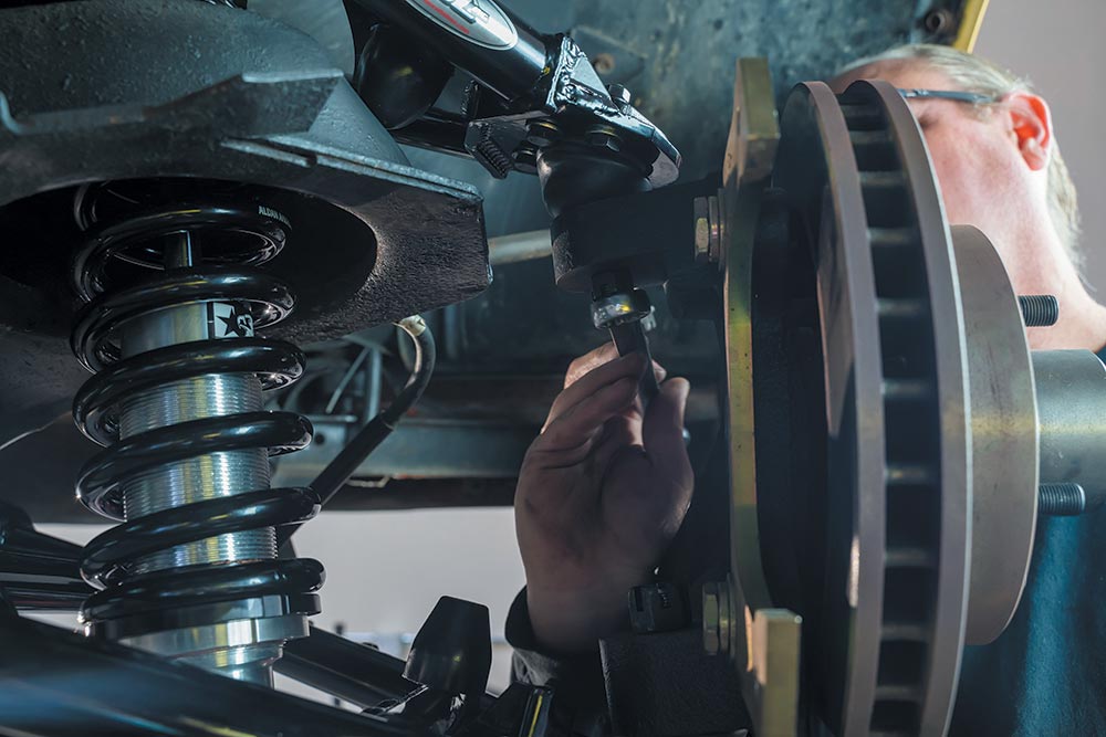
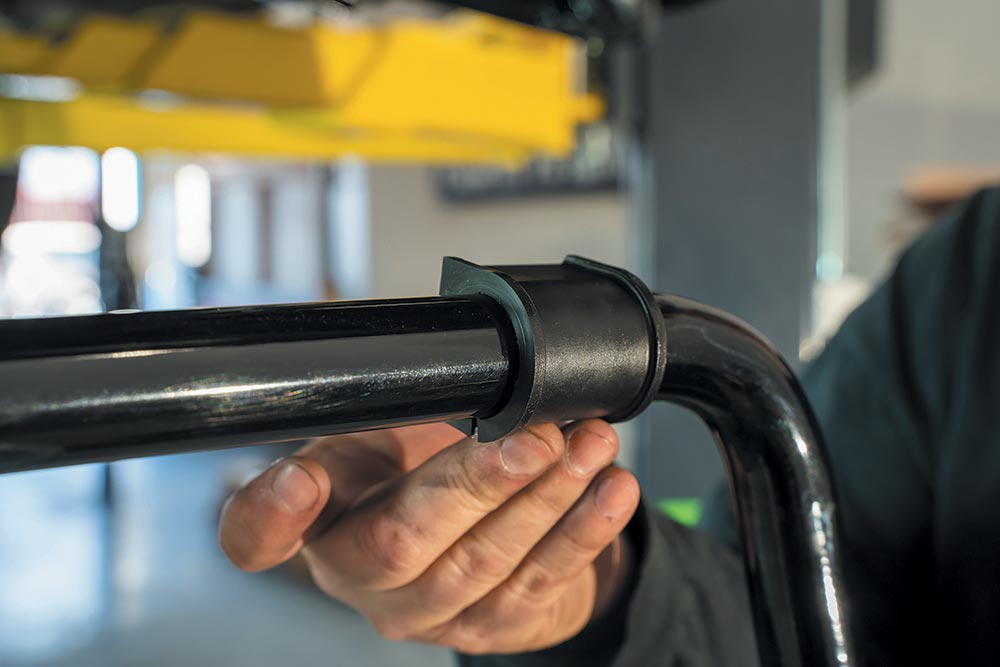
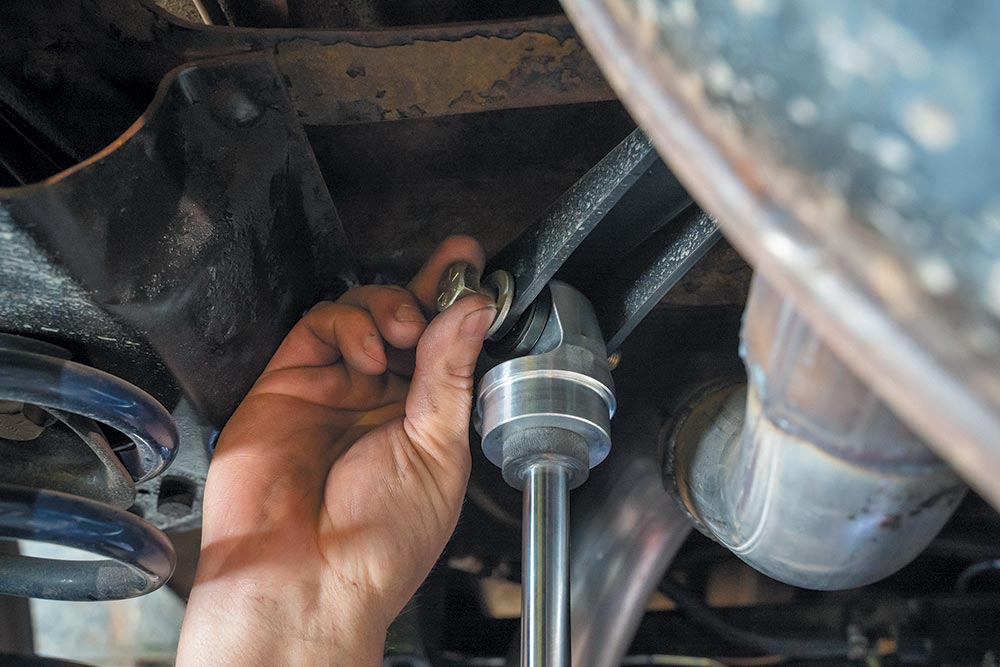
UPPER A-ARM REPLACEMENT
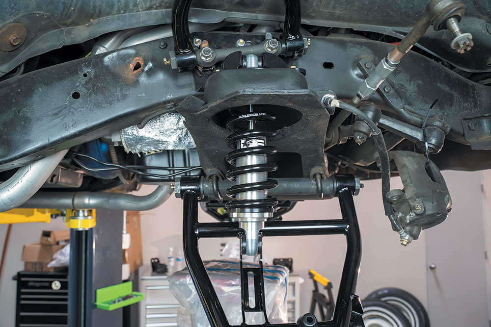
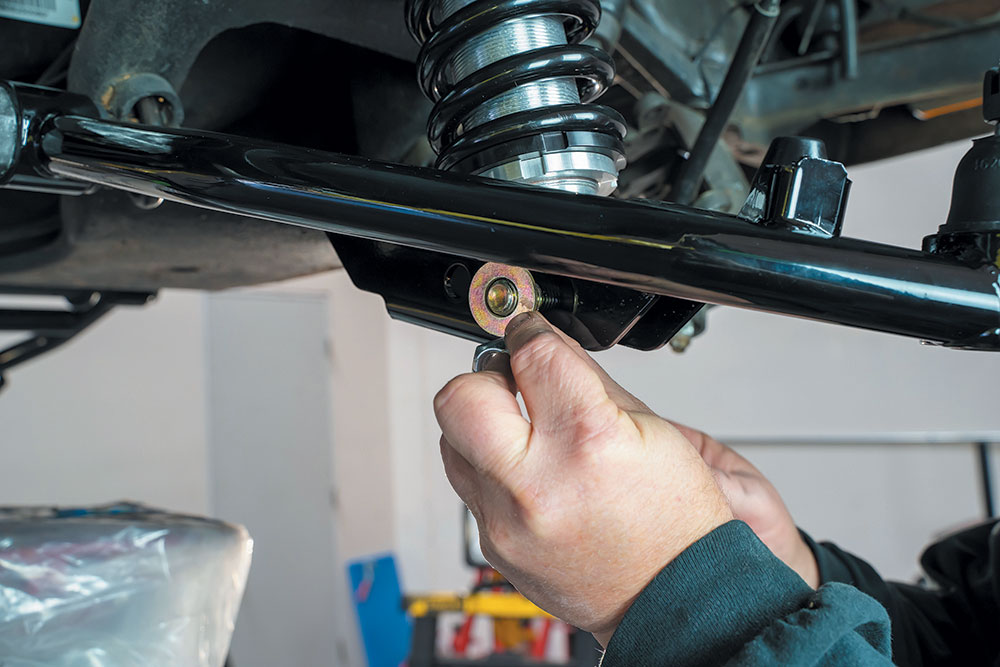
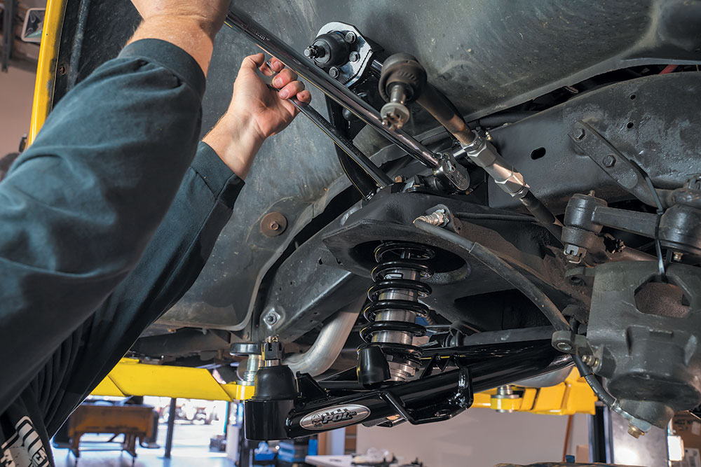
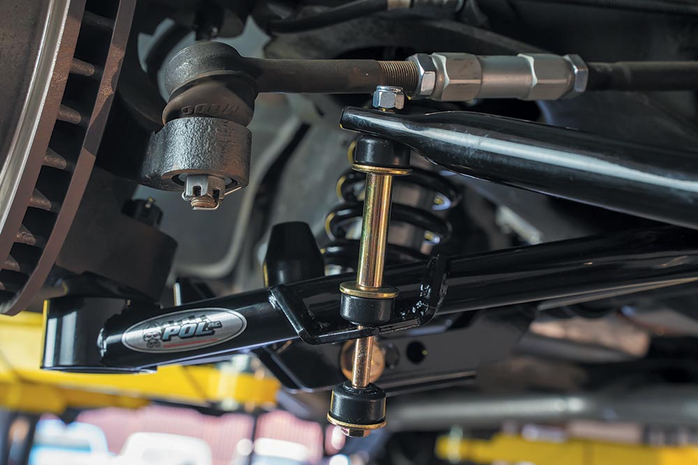
LOWER A-ARM AND COILOVER SHOCK INSTALL
Tools for the Job
- Floor jack or lift
- Jack stands
- Tire chock
- Torque wrench
- Socket set
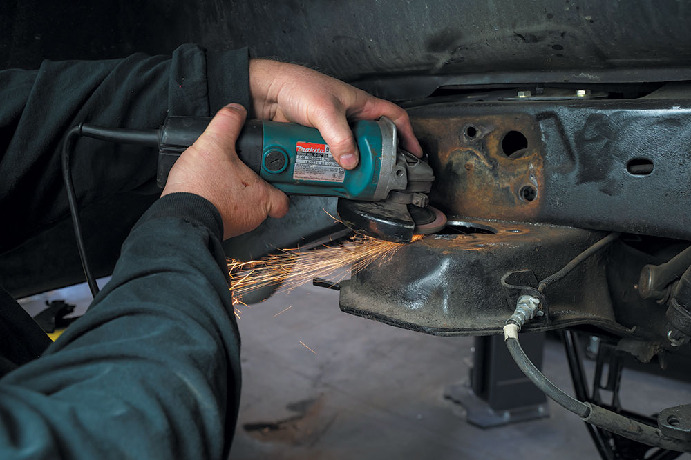
- Drills
- Half-inch drill motor
- 4-inch hole saw
- Other basic hand tools
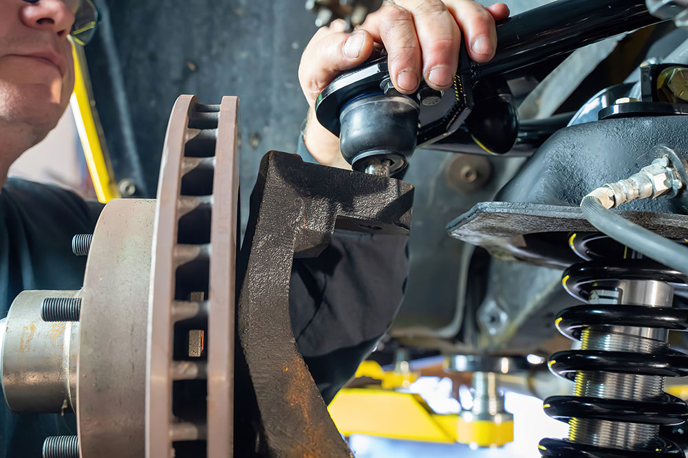
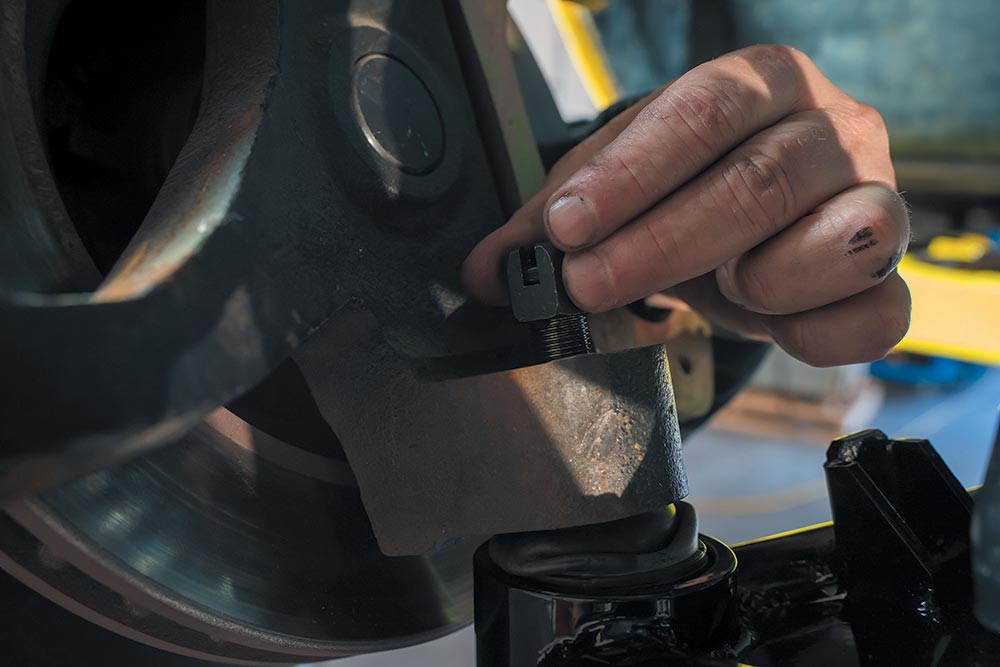
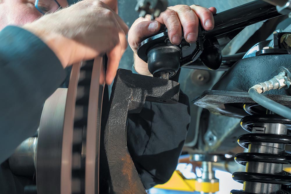
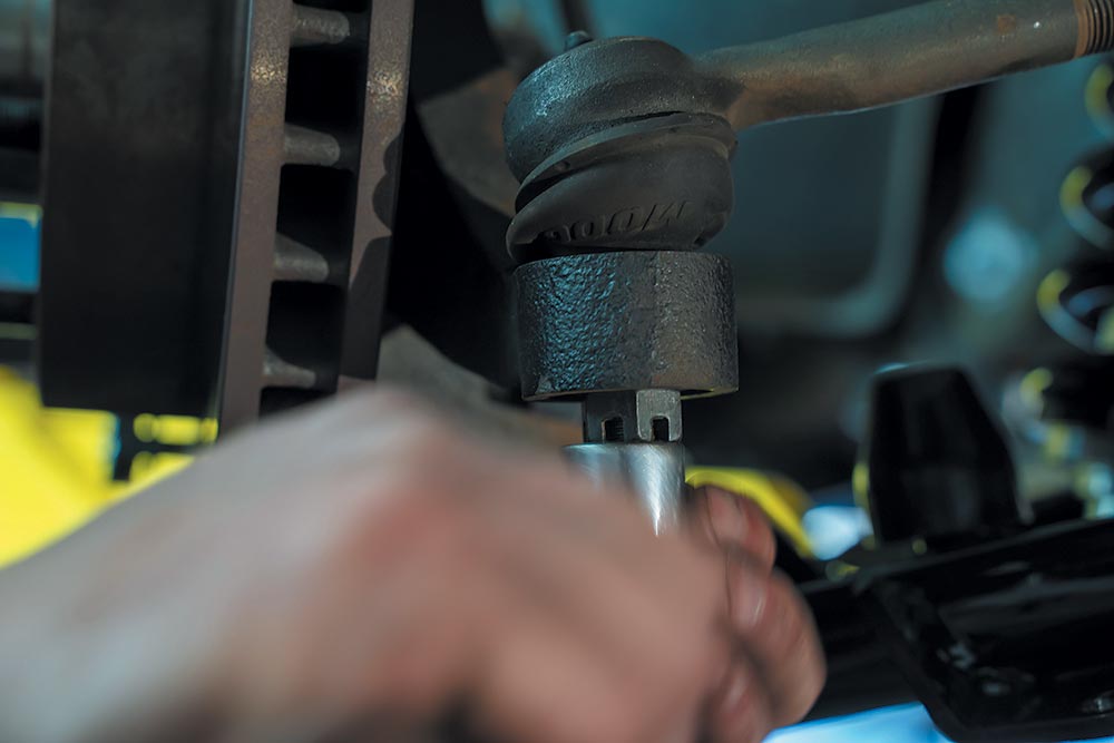
SPINDLE AND BRAKE ASSEMBLY
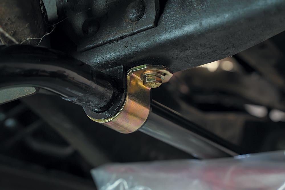
SWAY BAR
The OE sway bar won’t work with these A-arms. The new 1.125-inch 4140 heat-treated steel front sway bar minimizes body roll while improving handling and control, and is available separately.
TIP
Change the brake lines and hoses when installing new brakes. Converting from drums to discs will require lines, hoses, a master cylinder, and a proportioning valve that works with the new brakes.
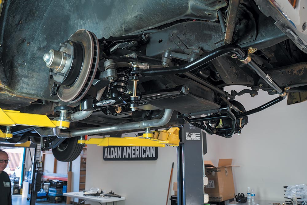
FINAL ASSEMBLY
Make sure all the hardware is tight, there’s no interference or binding in the suspension and steering, and the brakes are installed, bled, and operating correctly.
Bringing up the rear
Aldan’s TruLine series shocks (PN100108 MSRP: $245.95 each) for ’63-’87 Chevys and GMCs are American made, smooth riding, performance shock absorbers. TruLine Series shocks come in stock, lowered, and custom lengths, and are rebuildable, serviceable and backed by a lifetime guarantee.
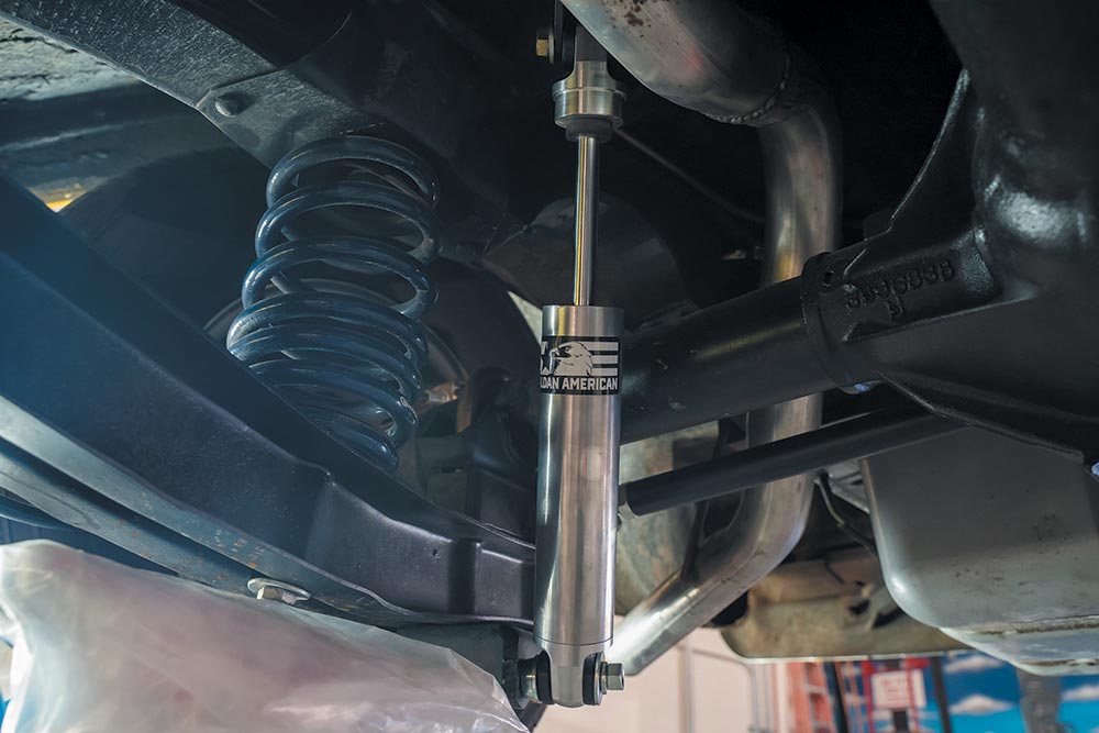
SETTING RIDE-HEIGHT
- The lower A-arms should be close to parallel with the ground, a good starting point for ride height.
- Align the front end immediately following installation.
ALIGNMENT SPECS
Camber
- -1/8 to -1⁄4º street use.
- -1/4 to -1º track use depends on conditions and driving style.
Caster
- + 4.5 to 8 degrees street use with additional 1⁄2º stagger to right side.
- Track use depends on conditions, driving style with caster without stagger.
- Toe 1/8” total toe in.
Source: Street Trucks Magazine